Checklist
Index
- Introduction
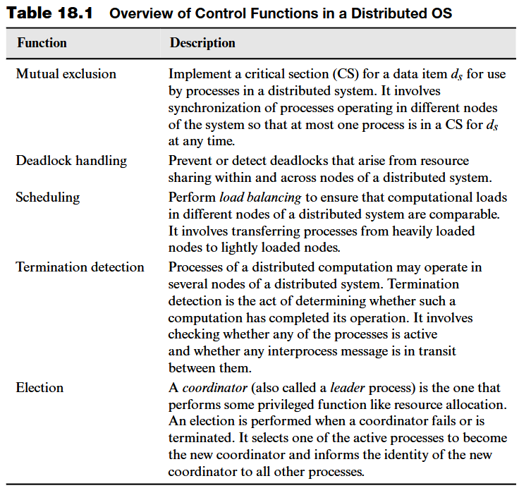
- Overview of Control Functions in a Distributed OS
- Parts of a process
- Correctness of distributed control algorithms - Liveness and Safety
- Ricart-Agrawala Algorithm → a process ask all other processes if he can enter the critical section
- Quorum based algorithm → improvement of Ricart-Agrawala, less messages
- Maekawa Algorithm → Balanced Coterie (improvement of quorum based), more centralized but less messages
- Token-based centralized algorithm → Algorithms in ring or inverted tree topology that pass a token to each others
- Ring Algorithm → A token is passed in ring, the token is a queue
- Raymond Algorithm → The root possess the token and pass it its immediate childrens, each node has a local queue of requests their or of their childrens.
- Token-based distributed algorithm - Suzuki-Kasami Algorithm → token-based, timestamp based, uses two vector clock to keep track of pending requests and satisfied request, and a global query of nodes. The latter two are part of the token.
- Bully Algorithm → Election of the leader, each process try to elect itself but they renounce if another process has higher id
- Election Algorithms for Ring Topology → The leader id is sent across the ring, the one with the highest is choosed
- Variant Highest Id Variant in which a process passess, through his channel, the id only if it’s greater than their own, or it passes their own.
IoT2 - Theory - Lecture 6 - Distributed Control Algorithms
- Slide lez 6
- Chapter 18 Dhamadhere
Introduction
Midterm Exercises
The algorithms shown in this section are topic of the midterms. A possible exercise is, given process, the time at which they make a request and the time they stay in critical section, shows all the steps until the last process quit the CS.
Every algorithm from this lecture could be in the midterm.
A distributed operating system performs several control functions.
Of these control functions:
- The mutual exclusion and deadlock handling functions are similar to those perfomed in a conventional OS.
- Scheduling function performs load balancing to ensure that computational loads in all nodes of the system are comparable
- The election function elects one among a group of processes as the coordinator for an activity
- The termination detection function checks whether processes of a distributed computation operating in different nodes of the system have all completed their tasks
To respond speedily and realibily to events occurring in a distributed system, a distributed OS performs a distributed control algorithms. The actions of this algorithms are performed in several nodes of the distributed system.
Distributed control algorithms depend on local states of different nodes, and use interprocess messages to query the states and make decisions. The correctness of the algorithm must be proved to ensure that they arrive at the correct decision.
Overview of Control Functions in a Distributed OS
Parts of a process
The following terminology is used to distinguish between actions of a client and those of a control algorithm:
- Basic computation: performs the application part of the code
- Control Computation: partecipate to the implementation of the distributed control algorithm
For example, consider the mutual exclusion problem: multiple process share a common resource, such as access to specific data. At the application level, an instruction grants access to this data. However, to ensure mutual exclusion, a process must coordinate with others requesting access to the critical section (CS) to determine the next process allowed to enter. The part of the process that coordinate the process with others is the control part.
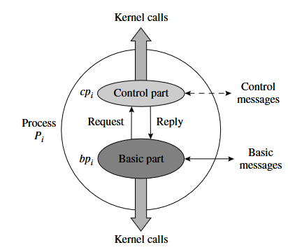
- The control part of a process
, requests access by asking other processes, “Can i enter the critical section?” If a receiving process is not interested in the CS, it responds with something like “OK for me”
When the basic part
While the basic part may become blocked when requesting a resource. the control part of a process never blocks, ensuring it can always respond to relevant events in a timely manner.
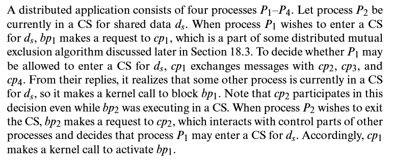
Example: basic and control parts of a process
Correctness of distributed control algorithms - Liveness and Safety
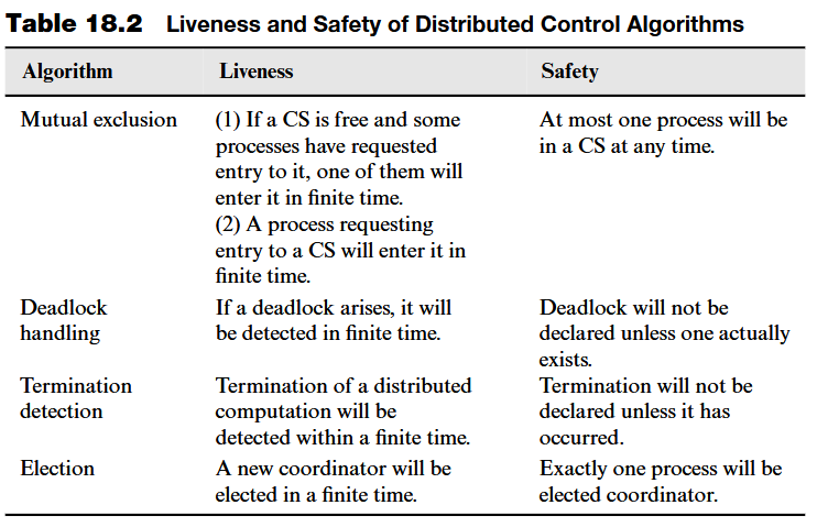
Two aspects of correctness are called liveness and saftey:
- Liveness: the algorithm will eventually perform correct actions, i.e, perform them without indefinite delays
- Safety: the algorithm will never take the wrong decision
A practical example of these properties:
 We model each algorithms as set of rules, that are performed only if there is a certain condition
Here is the notation:
<condition> : <action>
Using the notation
- Liveness: For all rules,
it means that will eventually be performed if holds. - Lack of safety: For some rule,
i.e may be eventually perfomed even if condition does not hold.
Ricart-Agrawala Algorithm
The algorithm is fully distributed (no coordinator): all processes partecipate equally in deciding which process should enter a CS next.
The idea of this algorithm is very simple: a process sends a message to all other processes, requesting permission. Before a process can enter the CS,
Mutual exclusion is ensured because at most one process can receive
Each message is timestamped, allowing requests to be ordered. If a process is already in the CS when it receives a request, it places the request in a queue, ensuring First-Come, First-Served (FCFS) access.
The FCFS ordering guarantees liveness, meaning that all processes will eventually gain access to the CS. Each process maintains its own queue of requests.
Steps of the Algorithm
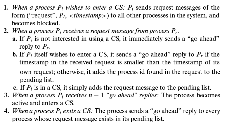
Ricart-Agrawala - Example 1
In a system with three processes, if P1 is in the critical section (CS) and P2 requests access, P1 cannot grant it immediately. Instead, P1’s control mechanism queues P2’s request as pending. If P3 does not need access, it simply replies “go ahead” to P2’s request.
Later, if P3 also requests access, it sends requests to both P1 and P2. Since P2 is still waiting, it checks timestamps and sees that its request has priority over P3’s. So, P2 queue the request of P3 and keeps waiting. Also P1, who is already in the CS, queue the P3 request after the P2 (because of timestamping).
When P1 exits the CS, it notifies its control mechanism, which then sends reply messages to both P2 and P3. Since P2 has the oldest request, it enters first, while P3 waits until P2 finishes, ensuring that access follows the correct timestamp order.
Ricart-Agrawala Example 2
Let’s see now the example considering timestamp
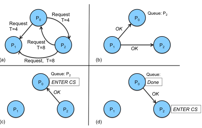
- (a)
- P0 send a request at time T=4 to P1 and P2
- P2 send a request to T=8. so it should go after.
- Since the timestamp of P0 is T=4, so it enter first in the CS
- (b)
- P1 receive a request from both P0 and P2, but because P1 is not interested, immediately responds to both P0 and P1.
- Note: the request is send as soon as it arrives, (i.e at T=4, P1 will send the OK reply to P0)
- (c)
- P2 confronts the timestamp and see that the P0 request has a lower timestamp than its own:
, so it sends the OK to P0 - P0 has now received the OK from both P2 and P1, so it can enter the CS and also queue the P2 Requests.
- P2 confronts the timestamp and see that the P0 request has a lower timestamp than its own:
- (d)
- Once P0 is finished, it sends a “go ahead” message to P2 (whose request was enqueued).
- P2 since has received an OK from everyone else, it enters the CS
If for instance in (c), both P1 and P2 want to enter the critical section, at the same time. P1 sends a message to both P0 and P2, with timestamp T=10. P0 enqueed the request (that will be
Note that these timestamps are managed using logical clocks, ensuring that no two process send a message at the exact same time. As a result, a message cannot be sent and received simultaneously.
The problem of this algorithm is the high number of messages. A possible workaround is to reduce the number of messages using the quorum approach
Quorum based algorithm
- Idea: request access to the critical section to a subset of processes called request set
- Problem: how to build the request sets, i.e select the processes belonging to each request set
- Solution: build non-disjoint request sets such that at least one process belongs to two or more request sets.
Let
- a Quorum
is a subset of - A Coterie
is a set of quorums
Properties of a coterie:
- minimality: no quorum is a subset of anther quorum
- intersection: the intersection of each pair of quorums is non void.
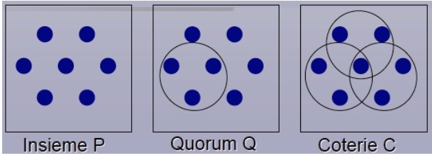
A process
The algorithm uses the following rules to ensure safety:
→ all process must belongs to atleast one request set → for each pair of process, the intersection of their request set must be not null

Note that, the central process, shared across all quorums, ensures that no process gains access to the critical section unless every relevant quorum permits it. Since this process sits at the intersection, it has visibility over all request queues.
This distributed algorithm does not distribute responsibility equally among processes. The central process plays a distinct role, bearing greater responsibility and workload compared to the others.
Maekawa Algorithm
The idea is to find a Coterie, that guarantees equal effort, and equal responsibility for all the processes that take part to the algorithm.
Given
(non void intersection as before) - Equal effort:
where is the number of processes in each request set - Equal responsibility: each
, belongs to the same amount of requests set per - Minimize the number of messages: for each
, belongs to
Maekawa proved that the optimal solution that minimizes the value
From which the value
For example, if
For example, 
Rules of the algorithm
Over this organization, we have to define the rules of the algorithm
3 types of messages: request, reply and release.
When a process
When a process
- it is active in the critical section
- OR has already sent a REPLY messages to another process.
In the latter case,
To release the critical section, a process
When a process receives a RELEASE message, the first request is dequeued and a REPLY message is sent to the process.
Proof of safety by contradiction
Let, for contradiction,
From the coterie intersection property:
Problem of the algorithm (deadlock)
The algorithm could lead to a deadlock, when all processes request the access to the critical section at the same time.
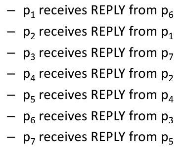 Each process receives only one of two REPLY messages, so no process can progress and there is a deadlock.
Saunders 1987 proposed a variant of the algorithm deadlock-free that emplys the happened-before (timestamp) relationship.
Token-based Algorithms for Mutual exclusion
Token
A token represents the privilege to use CS; only a process possessing the token can enter the CS.
The token guarantees the safety but not liveness. Liveness is a property of the algorithm rules that uses the token.
The processes have to be organized in a such way that, each request to enter the critical section must arrive from a process with the token.
So an abstract model (overlay network) must be first considered. This logical model is an abstract unidirectional ring model.
The token, is an object (a data structure) containing the queue of the pending requests.
Ring Topology
The edges represents the unidirectional channel that a process uses to comunicate with the following node in the ring
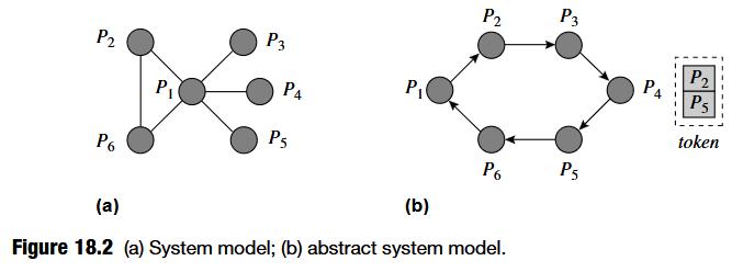 Recall that, with the topology of ring, each process can be reached with a finite number of message.
Algorithms steps
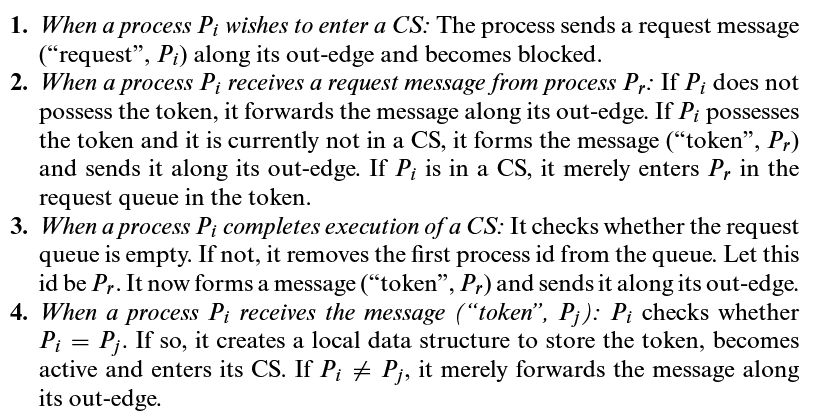
Example
If
If
The liveness is guaranteed by the abstract view of the system. Since the ring is closed, and the token is passed after a process finishes using the CS, the token will eventually arrive to the process that request the access of the critical section.
Raymond Algorithm
Inverted Tree and token holder
Uses an abstract inverted tree as the system model.
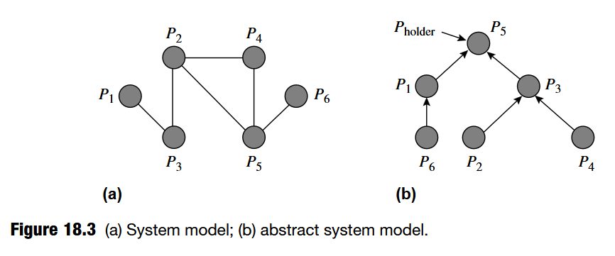 An inverted tree differs from a conventional tree because its edges point from each node toward its parent, rather than from the parent to its children.
Why this structure? The tree has a single root, which is the process holding the token. At any moment in the algorithm, the root represents the token-holding process, denoted as
Each child (that want to enter the CS) send a request to his parent, that propagates the request to his father, until it reaches the root.
Raymond’s algorithm has four key features:
- invariants that ensure that a request reaches
- a local queue of requesters in each node
- features to reduce the number of request messages
- provisions to ensure liveness
Raymond Algorithm - Steps of the Algorithm
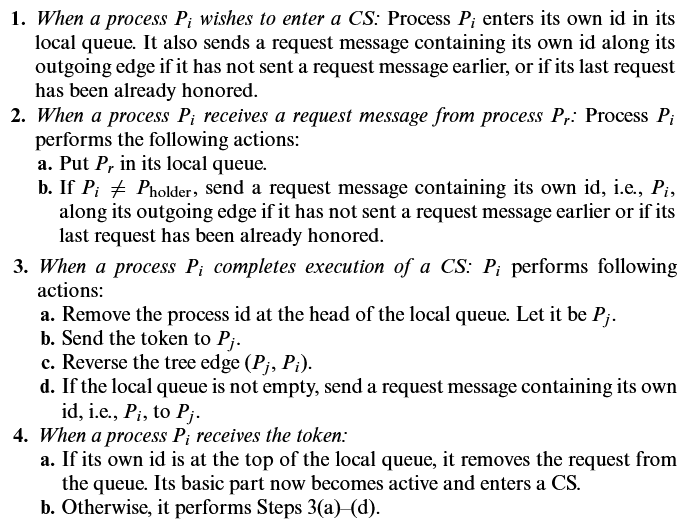
In step 3, after a process
Example of Raymond Algorithm
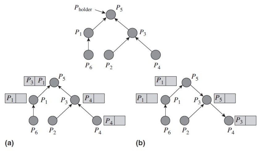
is the holder and is in critical section, with and in its queue (meaning they have both made requests). - (a) Let’s analyze the request coming from
. has in its own queue, this means that has itself made a request to enter the critical section. - Recall that
doesn’t propagate the id but its own id. - Why? Because
only knows his immediate childs, it doesn’t know who is
- (b) Once
quits the critical, becomes the new root of this tree, inverting the edge. will then check its own queue, extract and propagate the token to and invert the edge . - Since
is the only process in its queue, it enters the critical section
- (b) To guarantee the liveness,
must receive the token in a finite number of step. When sends the token to and change the edge, it also send a request for itself that is enqueued in . - When
sends the token to , because there is another request, it also send a request to with its own id. And so , after he finished and extract first id from its queue, will send the token to once it has finished the actions in the CS. - The same does
for and same to , that finally receives the access to the critical section.
Token-based centralized algorithm
In this centralized approach, we have a specific process called coordinator that handles the token. The coordinator keeps track of the requests submitted (but not yet served) and requests served.
Each process
When a process
On exiting the CS,
Coordinator
Data structure:
: stores the list of the requests submitted but not yet served : the vector of length equal to the number of process. Position V[i]stores the number of request already served for process
Rules:
requests the token - when
request is eligible and the coordinator has the token, sends it to
Client
Data Structure:
: timestamp vector clock Rules: - Token Request:
and sends VC to the coordinator - Token reception: enters CS
- CS exit: sends token to the coordinator
Example
- Let the process be Coordinator,
, increases and send the request to the coordinator  What if P2’s request arrives before P1’s? Since we are using vector clocks, P1 sends its request with a timestamp of (1,0), but the first request to reach the coordinator is from P2, with a vector clock of (1,1).
The coordinator then compares this vector clock with its request list, which tracks already satisfied requests. By doing so, it determines that P2 has requested access, but there is a pending request from P1 that has not yet been served. Because P2’s message arrived first, the coordinator knows that a request from P1 must have been sent earlier.
As a result, P2’s request is not yet eligible for execution. Since the communication is reliable, eventually P1 request will arrive, containing the vector (1,0) and becomes eligible.
 Once the request has been served and the token is passed back to the coordinator, it’s the turn of P2.
Another interesting scenario arises when P1 and P2 do not communicate with each other. In this case, P2 cannot update its own vector clock with requests made by P1. When P2 wants to request access to the critical section, it simply increments its own position in the vector clock, resulting in (0,1).
If this request (0,1) arrives at the coordinator, the coordinator’s request list initially contains (0,0). Now, with the arrival of (0,1) from P2, the request becomes eligible because, at this point, no other process has requested access to the critical section.
However, if we later compare P1’s request (1,0) with P2’s request (0,1), we see that neither vector dominates the other. As discussed in the lecture on vector clocks, this means that no message has been exchanged between P1 and P2 regarding their requests. Therefore, these two requests are considered concurrent, and the coordinator can sort them as he wants.
Safety is guaranteed by the token. Liveness is guaranteed by the happened-before relationship and by the presence of the token.
This is an example of algorithm based on the use of the vector clock. An extention to this algorithm, also token-based but completely distributed is the Suzuki-Kasami algorithm.
Token-based distributed algorithm - Suzuki-Kasami Algorithm
The needed data structures are stored into the token, that is passed to each process. When a process wants to enter the CS and does not hold the token, sends a broadcast message. The process that holds the token, if not in the CS, replies with the token, while if it is active in the CS releases the token after exited.
Data structure of the process
: vector of length , where stores the sequence number of the last request submitted by process
Data structure into the token:
: vector of length where stores the sequence numer of the last fulfilled request of process : queue of pending requests
Suzuki-Kasami Example 1 with 3 processes
For example, if we consider three processes,
Note: in this example i omitted it, but also  Inside the token we also have a queue of pending requests, so each time a process request to access the critical section and this is not immedietaly served, this request is enqueued. So for example, if in Q i have process p2, it means that it has submitted to enter the critical section but this request has not been served.
Say that 
At this point, say that 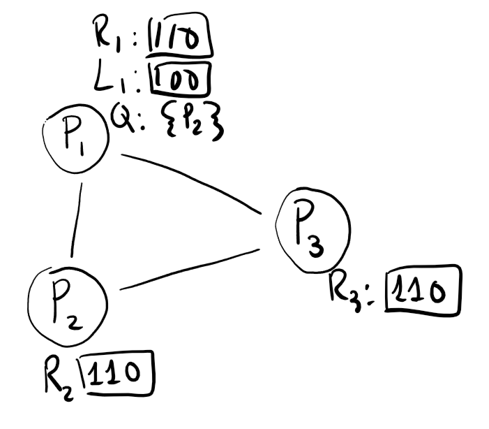
Say that,
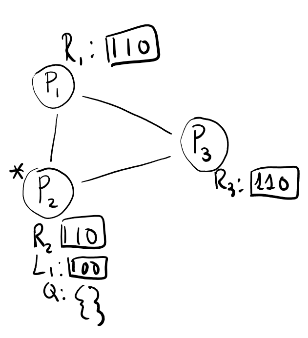 Upon the exit of the critical section by
Note that these two structures that in previous algorithm were mantained by a coordinator, are now shared between processes inside a token.
Suzuki-Kasami rules
Rules for process
Token Request
- increase its own counter - For each
send (Request, , ]) - all processes receive the request
Token Request from
- if
holds the token AND it is not in CS AND , send the token
Exit CS:
(request fulfilled) - For each
not in , is enqueued in Q if (there is a pending request). - If Q is not empty, dequeue
and send to it the token - If Q is empty,
hold the token.
Suzuki-Kasami - Example 2
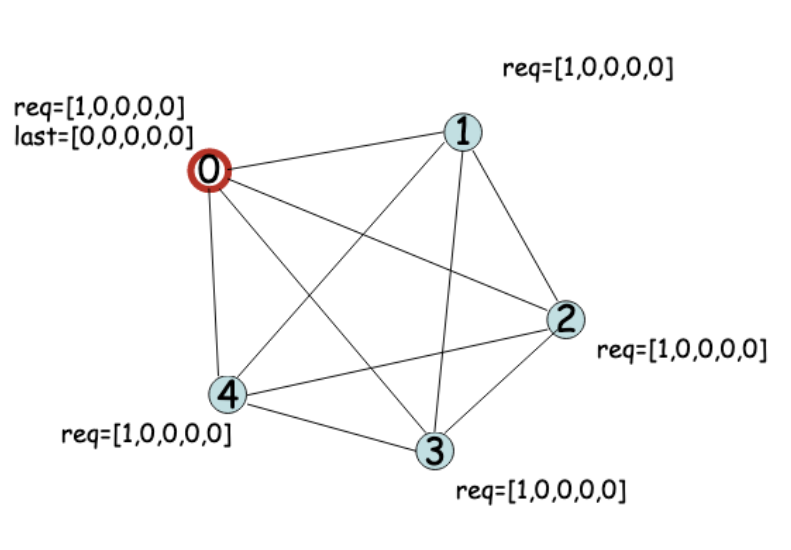
- P0 holds the token (red circle). The vector L=last, and R=req. At this time the queue is empty.
- There is a pending request made from P0, if
so it means that it can enter the critical section and P0 holds the token. During the execution of the critical section, p1 and p2 sends request to enter the CS:
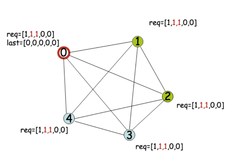
- Note that p1 and p2 sends a msg to all process, so they ALL update req.
- P0 exit the critical section
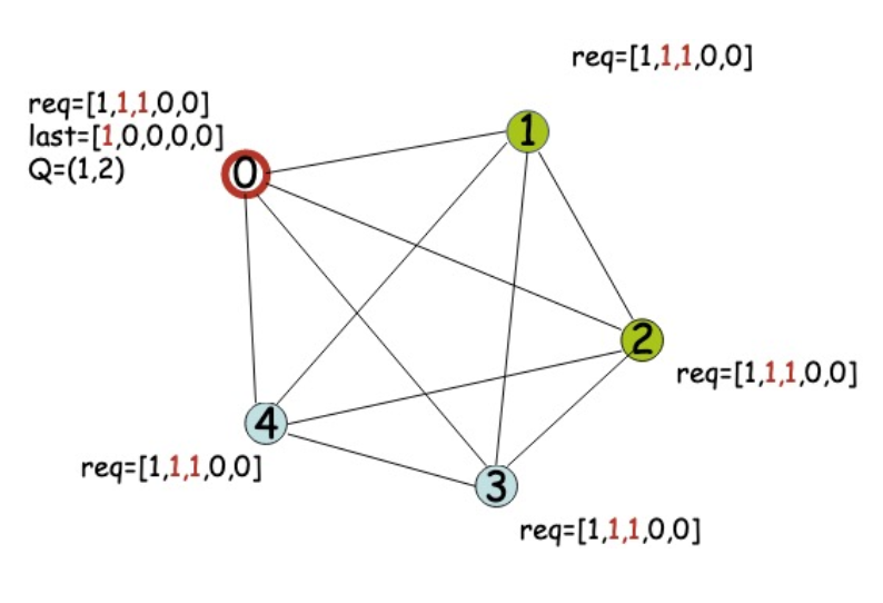
- Insert last two requests (1,2) in the set
- scan its own request here (req) and all the time, the request is equal to
— this is interpreted as there is a pending request from p1 (req) but has not be fullfilled ( ) - For p3 and p4 there are no pending requests.
- After this, P0 scan the
and send the token to P1.
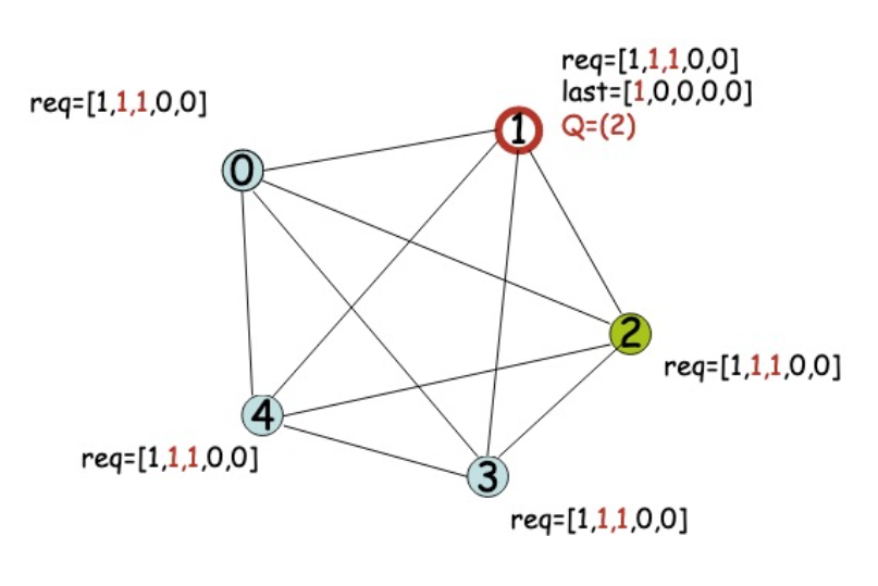
During the execution of the CS, other request arrives
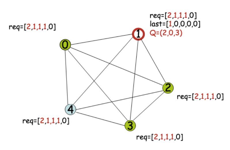
- When the critical section is terminated, the queue is updated
- Note that P2 was already in the queue so is not inserted there again, only 0 and 3 are added
- After this the token is sent to 2

Safety and liveness
Safatey is guaranteed by the token Liveness is guaranteed by the queue of pending request and the presence of the token
Leader election
Even though centralized algorithms are not always the most efficient choice, they are often useful because they reduce the number of messages exchanged (more efficient). When using a coordinator-based algorithm, all participating processes must also implement a leader election algorithm to ensure that a new coordinator can be selected in case the current one fails.
As long as there is a leader election algorithm, where all process partecipate to the decision in case of failure, the leader election approach is viable.
This means that every process must include the logic required to assume the coordinator role if necessary. This concept is also present in Zookeeper, a Hadoop module designed for distributed coordination, which implements a leader election algorithm to ensure a new coordinator is chosen in case of failure.
To determine the coordinator, we need a clear rule. Election algorithms are based on some definition of priority. For example, the coordinator is the process with the higher id (or any other kind of priority).
Bully Algorithm
The election algorithm starts at the moment a process verify that the coordinator is inactive. If a process
A process
If it receives a response, it waits to receive a message informing it which process with higher priority than its own has been elected coordinator.
Bully Algorithm - Example
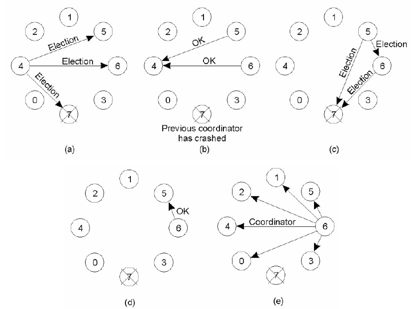
starts the elections, it send a message only to and (that we assume is down, hence the X). will not be involved in the election, their id is lower. (You see now why it’s called bully, is trying to elect itself). and receive a msg from , they send a OK response to , so they know for sure that will never be the new coordinator (bro is never gonna make it) and stop his election. - Now,
and starts the election, (see (c)), but wins (since it sends OK to , stopping his election)
What happens if in the future
Election Algorithms for Ring Topology
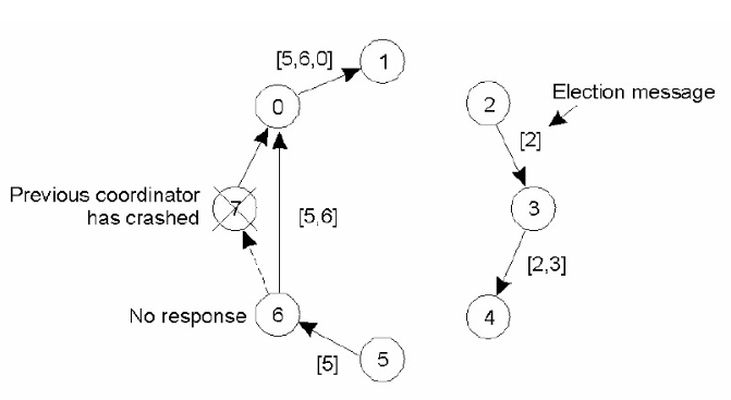
Consider a unidirectional ring topology. Processes have a unique ID and are logically organized in a ring. Every process knows its neighbors and the coordinator is the process with the highest ID.
The ELECTION message is sent to each successor until a live node is found. Each process adds its own ID to the message. The message returns to the process that initiated the election which chooses the coordinator as the process with the highest ID. So it send a message communicating the new coordinator.
There may be multiple elections in the case of system partitioning. We assume that the ring is split due to the failure, meaning different sections of the system might attempt to elect their own coordinators. However, having multiple coordinators in different sections would result in an inconsistent state, which is not allowed in every distributed systems
Here’s a simple example
Variant: Highest Id
Each process sends its own identifier along the ring.
When a process
- If the values are different,
circulates the received identifier along the ring only if greater than its own, otherwise it replaces it with its own - If the values are equal,
declares itself the leader 
After